
Interested?
Need Help?
Documentation?


![]()
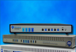
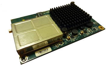
| ECMM9500-BC Features Embedded Cable Modem Module |
| Features | Specifications | Datasheet |
1. Operating Temperature Range
| Temperature |
|---|
| 0°C∼+40°C |
2. Interface
| Item | Specifications |
|---|---|
| Reset port (See 7.2.1) | Reset to restart/reboot the system when holding the reset longer than 1 second. |
| Console port (See 7.2.1) | Internal Console port. |
| JTAG port (See 7.2.1) | Internal JTAG port. |
| GMII for LAN Ethernet port (See 7.2.2) | GMII for 10/100/1000Base-Tx Ethernet port. N-way, Automatic speed negotiation supported. Auto-sensing, auto-detection MDI/MDI-X. |
| Cable connector (See 7.2.3) | RF F-type, female, 75 ohm. |
3. Cable Specification
Compliant with DOCSIS 3.0/2.0/1.1 standards
4. Downstream (Receiver) and Upstream (Transmitter) Characteristics
| Item | Downstream | Upstream |
|---|---|---|
| Frequency Range | North America: 88MHz~1002MHz Europe: 108MHz~1002MHz Japan: 91MHz~1002MHz |
North America: 5MHz~42MHz Europe: 5MHz~65MHz Japan: 5MHz~65MHz |
| Channel bandwidth | DOCSIS: 6 MHz EuroDocsis: 8 MHz |
TDMA: 200, 400, 800, 1600, 3200 and 6400 kHz S-CDMA: 1600, 3200 and 6400 kHz |
| Impedance | 5 ohm (nominal) | ohm (nominal) |
| Modulation | PSK,64/256QAM | K, 8/16/32/64/128 QAM |
| Maximum Data Rate | 320Mbps, 8 channel bond | 0 Mbps, 4 channel bonding |
| Symbol Rates | 64QAM: 5.057Msym/s 256QAM: 5.361 Msym/s |
160, 320, 640, 1280, 2560 and 5120 ksym/s |
| FEC | RS (128,122) GF128 with Trellis coding | Reed Solomon |
| Signal Level | Receive Power Level: –15 dBmV ~ +15dBmV | Transmit Power Level: TDMA: +17 ~ +57dBmV (32QAM, 64QAM) +17 ~ +55dBmV (8QAM, 16QAM) +17 ~ +61dBmV (QPSK) SCDMA: +17~+56dBmV (all modulation) |
| Signal-to-Noise Ratio (SNR) | BER < 10^-8 64QAM: > 23.5dB 256QM: > 30dB |
5. Software Specifications
| Item | Specifications |
|---|---|
| Security | DOCSIS Baseline Privacy Plus: 1024-bit RSA and 128-bit Triple-DES for BPKM protocol 56 -bit DES for data encryption X.509 v3 certificates |
| DOCSIS | Compliant to DOCSIS 3.0 |
| Protocol | IP, UDP, ARP, ICMP, DHCP, SNMP, TFTP, TOD, BOOTP, SYSLOG |
| Configuration | Ease of configuration and privacy control provided by resident or downloaded code from a Cable Modem Termination System (CMTS) |
| Bridging | Support for unicast, broadcast, and multicast IP packets Variable-length packet cable Media Access Control (MAC) transport layer Mix of contention and reservation-based upstream transmission |
| Quality of Service | Quality of service of MAC layer |
| Management Operations (SNMPv1/v2c/v3) | RFC1157: A simple Network Management Protocol RFC1901: Introduction to Community-based SNMPv2 RFC3416: Version 2 of the Protocol Operation for the SNMP RFC3417: Transport Mapping for the SNMP RFC2578: Structure of Management Information Version 2 RFC2570: Introduction to Version 3 of the internet-standard Network Management RFC3411: An Architecture for Describing SNMP management Frameworks RFC3412: Message Processing and Dispatching for the SNMP RFC3413: SNMP Applications RFC3414: User-based Security Model (USM) for SNMPv3 RFC3415: View-based Access Control Model (VACM) for SNMP RFC2576: Coexistence between Version 1, Version 2, and Version 3 of the Internet-standard. Network Management Framework |
| MIBs support | C1493: BRIDGE-MIB RFC3418: SNMPv2-MIB RFC2011: IP-MIB RFC2013: UDP-MIB RFC2233: IF-MIB RFC3411: SNMP-FRAMEWORK-MIB RFC3412: SNMP-MPD-MIB RFC3413: SNMP-TARGET-MIB SNMP-NOTIFICATION-MIB RFC3414: SNMP-USER-BASED-SM-MIB RFC3415: SNMP-VIEW-BASED-ACM-MIB RFC2576: SNMP-COMMUNITY-MIB RFC2665: EtherLike-MIB RFC2669: DOCS-CABLE-DEVICE-MIB RFC2786: SNMP-USM-DH-OBJECTS-MIB RFC2851: INET-ADDRESS-MIB RFC2933: IGMP-STD-MIB RFC3083: DOCS-BPI-MIB DRAFT: DOCS-IF-MIB DRAFT: USB-MIB DRAFT: DOCS-BPI2-MIB DRAFT: DOCS-QOS-MIB Append L/Annex H: DOCS-IF-EXT-MIB Append L/Annex H: DOCS-CABLE-DEVICE-TRAP-MIB |
6. Power Consumption and Physical Dimensions
| Item | Specifications |
|---|---|
| Power Consumption | Maximum: 5.64W at upstream power level of 51dBmv, 8×4 channel bonding, gigabit LAN port, and maximum upstream and downstream throughputs. Standby: 5.16W at 8×4 channel bonding, gigabit LAN port (Shall comply with EU CoC spec Tier 2, shall comply with Energy Star 2.0). |
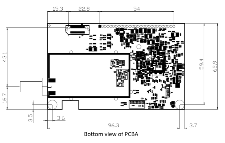
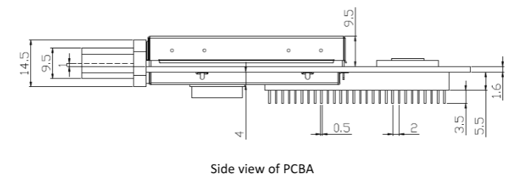
| PCB Dimension | • Excluding the RF connector – 100mm x 62.9mm x 20.1mm (3.94inch x 2.48 inch x 0.8inch) • Including the RF F connector – 119.9mm x 62.9mm x 20.1mm (4.72inch x 2.48 inch x 0.8inch) |
| Weight | 0grams |
7. Physical Specifications

7.2.1 Main connector: Power and I/O_J7
| Pin | Function | I/O | Pin | Function | I/O |
|---|---|---|---|---|---|
| 1 | +3.3Vdc Input | I | 2 | +3.3Vdc In | I |
| 3 | CM Reset | I | 4 | Ground | |
| 5 | +3.3Vdc Input | I | 6 | EJTAG_TMS | I |
| 7 | EJTAG_TDO | O | 8 | EJTAG_TDI | I |
| 9 | EJTAG_RTCK | O | 10 | Reserved | X |
| 11 | Reserved | X | 12 | JTAG_TRSTN | I |
| 13 | Ground | 14 | +3.3Vdc Input | I | |
| 15 | +3.3Vdc Input | I | 16 | +3.3Vdc Input | I |
| 17 | Ground | 18 | UART_RD | ||
| 19 | UART_TD | O | 20 | Reserved | X |
| 21 | Reserved | 22 | LAN indicator (for ESBC only) | O | |
| 23 | Upstream indicator (for LED) | O | 24 | LAN indicator (for LED) | O |
| 25 | On Line indicator (for LED) | O | 26 | Power indicator (for LED) | O |
| 27 | Downstream indicator (for LED) | O | 28 | Ground |
7.2.2 GMII Bus Connector_J8
| Pin | Function | I/O | Pin | Function | I/O |
|---|---|---|---|---|---|
| 1 | Ground | 2 | Ground | ||
| 3 | Ground | 4 | MDI_0+ for Giga PHY | I/O | |
| 5 | Ground | 6 | MDI_0- for Giga PHY | I/O | |
| 7 | Ground | 8 | Ground | ||
| 9 | Ground | 10 | MDI_1+ for Giga PHY | I/O | |
| 11 | Ground | 12 | MDI_1+ for Giga PHY | I/O | |
| 13 | Ground | 14 | Ground | ||
| 15 | Ground | 12 | MDI_2+ for Giga PHY | I/O | |
| 17 | Ground | 18 | MDI_2+ for Giga PHY | I/O | |
| 19 | Ground | 20 | Ground | ||
| 21 | Ground | 20 | MDI_3+ for Giga PHY | I/O | |
| 23 | Ground | 24 | MDI_3- for Giga PHY | I/O | |
| 19 | Ground | 20 | Ground |
7.2.3 RF Connectors_J9
| Pin | Function | I/O | Pin | Function | I/O |
|---|---|---|---|---|---|
| J9-1 | RF F-Type 75ohm | I/O |
